| Written by Mark Buzinkay
Table of contents:
- Define Scenarios Before Selecting Technology
- Create a Reliable Detection and Positioning Layer
- Turn Sensor Data into Safe Vehicle Decisions
- Protect Driver-Controlled, Remote and Autonomous Operations
- Integrate, Test and Sustain the System
- FAQ
- Takeaway
- Glossary
Define Scenarios Before Selecting Technology
Every implementation should start with a vehicle-interaction risk assessment. The mine identifies where people and machines can meet, how the encounter develops, its likely consequences and which existing controls can fail. Useful categories are vehicle-to-person, vehicle-to-vehicle, and vehicle-to-equipment or environment. These correspond with the underground functional-performance scenarios developed by EMESRT. (1)
Typical scenarios include vehicles approaching a blind intersection, an LHD reversing near a pedestrian, a technician entering an articulation area, or a vehicle approaching parked equipment. Other cases arise at drawpoints, crushers, workshops and fuel bays. Mines must also consider failed lighting, roadworks and missing or damaged personnel tags.
Each scenario should be translated into a functional requirement. The specification defines the objects to be detected, operating speeds, approach directions, gradients, visibility, maximum acceptable latency and required response. It also establishes whether the system should identify an object, issue a warning, reduce speed, stop movement or prevent a function from starting. Separate requirements may be needed for forward travel, reversing, articulation, boom movement and rotation.The distinction between collision warning and collision avoidance matters. A warning system informs the operator; an avoidance system can intervene in machine control. ISO 21815-1:2022 (2) covers object detection, operator warnings, automatic intervention and testing, although site-specific engineering remains necessary.
Controls should be layered. Road design, separation barriers, traffic direction, visibility, speed limits, right-of-way rules, access control and operator competence reduce the probability of an encounter. Technology addresses residual risk; it should not justify poor roadway design or uncontrolled pedestrian access. If the baseline controls are weak, the CAS will face frequent conflicts and nuisance interventions.
Detection distance cannot be one fixed number. It must account for speed, payload, grade, braking, system latency and human reaction. A loaded truck descending a ramp needs an earlier response than a slow utility vehicle. Requirements must also define a minimum-risk state when equipment fails.

Create a Reliable Detection and Positioning Layer
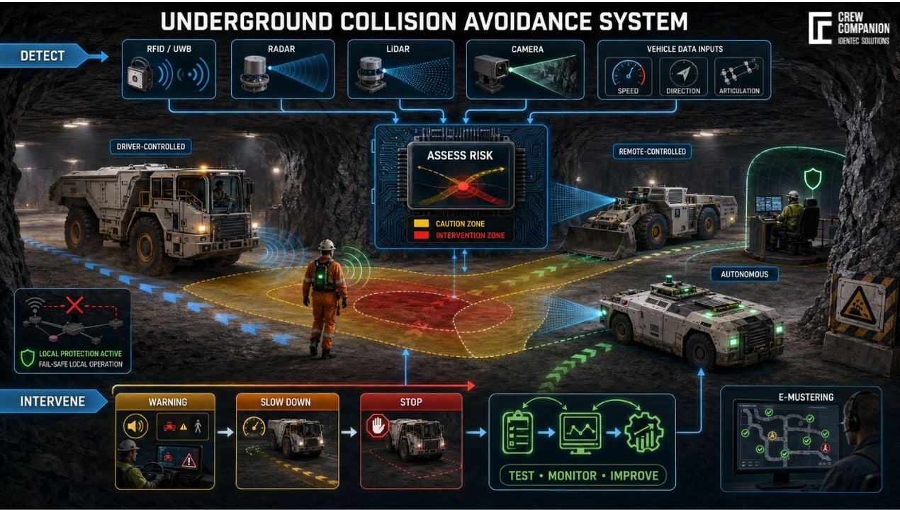
Underground detection can be cooperative, non-cooperative or a combination of both. Cooperative detection requires vehicles or people to carry compatible electronic devices. Examples include active RFID, low-frequency magnetic-field systems, Bluetooth Low Energy, and ultra-wideband. The devices exchange an identity or ranging signal, enabling the CAS to recognise a particular person or vehicle. Identity helps the logic distinguish a pedestrian from a haul truck and apply different rules.
Low-frequency magnetic systems can form defined warning or stop zones, but installation geometry, metal structures and machine configuration affect their fields. Active RFID is useful for identification and zone detection but may not provide precise direction or distance. BLE offers economical proximity functions, although obstruction and reflection can alter signal strength.
UWB estimates distance from signal timing and supports more precise relative positioning, including which side of a machine a person occupies. Mine-wide anchors can provide absolute coordinates, although they add survey, power, cabling and maintenance requirements.
Relative positioning measures the relationship between nearby participants, whereas absolute positioning places them in a mine coordinate system. Relative ranging can protect a machine even when the mine network is unavailable. Absolute positioning supports intersection rules, geofences, route planning and fleet-wide awareness. A robust architecture often uses both: local protection for immediate hazards and mine-wide location for context.Non-cooperative sensors detect untagged objects. Radar measures range and relative velocity and tolerates darkness and dust. LiDAR provides detailed geometry but can degrade in dense dust, spray, or dirty optics. Cameras classify objects but require illumination, clean lenses and suitable algorithms. Thermal cameras can help detect people, while ultrasonic sensors support short-range manoeuvres.
Vehicle data is another important input. Wheel speed, transmission state, steering angle, articulation angle, brake status and inertial measurements reveal how the machine is moving. On autonomous vehicles, localisation and planned trajectory can be shared with the CAS. On conventional machines, odometry can help determine whether a detected object lies in the actual path rather than merely near the vehicle.
Underground trials must test bends, grades, wet headings, metallic surfaces, electrical interference, tag orientation and antenna shadowing. Detection probability, error, false alarms and latency should be measured. Sensor fusion combines strengths: radio identifies a worker, radar confirms range and closing speed, and a camera classifies the scene. The logic must also handle conflicting inputs.
Turn Sensor Data into Safe Vehicle Decisions
The decision layer validates sensor health, associates detections with tracked objects and estimates their position, direction and velocity. It predicts path intersections, calculates time to collision, and compares available distance with what's required to warn, react, and stop.
Risk zones should therefore be dynamic. A caution area can extend with increasing speed, while an intervention area accounts for brake delay and stopping performance. Geometry must follow the machine’s movement. A reversing vehicle needs protection behind it; an articulating loader requires coverage around its changing crush zones; a turning machine needs a curved predicted path rather than a rectangular perimeter.
Context prevents unnecessary alarms. A person beside an isolated vehicle differs from someone behind a reversing LHD, while vehicles separated by rock cannot collide. Map matching, predicted travel, tunnel topology and machine state clarify the risk. Any alarm-suppression rule must be demonstrably safe and validated.
A useful response hierarchy begins with awareness, then escalates as risk rises. The operator may first receive a directional visual indication, followed by a distinctive audible or haptic warning. At a higher level, the CAS can limit propulsion, command controlled deceleration or inhibit a hazardous machine function. An emergency stop is the final response, not the default response to every detection; abrupt braking can create secondary risks involving unstable loads, following vehicles or passenger injury.
The interface must communicate urgency and direction immediately. Consistent colours, tones and symbols reduce confusion. Operators should understand what was detected and whether intervention is active. Non-credible warnings cause alarm fatigue and encourage bypassing, while faults, muted functions and degraded coverage must remain visible.
Safety-related control needs a defined interface with propulsion, braking, steering and implements. The design should specify command authority, response time, diagnostic coverage and behaviour after loss of power or data. ISO/TS 21815-2:2021 (3) defines an onboard J1939 communication interface relevant to collision warning and avoidance. Functional-safety analysis should then show that hardware, software and communications achieve the required performance for each safety function.
Protect Driver-Controlled, Remote and Autonomous Operations
Driver-controlled vehicles retain a human decision-maker, so the CAS primarily improves perception and reaction. It covers blind spots, identifies tagged personnel and warns about conflicting traffic. The system must be tuned to give the driver enough time without alarming for every harmless object at the roadside. If automatic intervention is introduced, it should be predictable, limited to defined risk conditions and verified against the vehicle’s braking capability.
Remote-controlled equipment changes the risk. The operator may stand nearby, work from a protected station or control the machine from the surface. Cameras replace direct perception but have limited views and transmission delay. The system must monitor zone boundaries, communications and access by other people.
Local remote operation needs particular protection against pinning and crushing. A wearable device can identify the operator, while machine-mounted sensing establishes whether that person is entering a hazardous zone. Directional zones can allow a safe machine function while inhibiting only the movement that would create contact. NIOSH research describes this more selective approach: an intelligent proximity system determines a miner’s position relative to a machine and turns off only unsafe functions rather than stopping all activity (NIOSH research paper (4)).
For tele-remote operation, command and video links need defined latency and fail-safe behaviour. Communication loss must cause a controlled safe state, not continued movement on the last command. Onboard detection remains essential because the operator may not see an untagged person, fallen material or vehicle.Autonomous vehicles must follow routes, detect obstacles, estimate free space and coordinate with other equipment—maps, LiDAR, radar, cameras, odometry and inertial sensing support navigation. Vehicle-to-vehicle messages can share position, velocity and intent, while traffic management can reserve road segments or intersections.
Central coordination is insufficient for immediate protection. Network delay, coverage loss or stale data must not prevent a vehicle from stopping for a local obstacle. Autonomous equipment needs onboard protection that can independently reach a minimum-risk condition and detect participants outside the autonomy network.
Mixed-mode operation is the hardest case. Autonomous, remote-controlled and driver-controlled machines may interpret right-of-way differently and provide different quality of position data. The mine needs common interaction rules, compatible identifiers and clearly controlled transition zones. ISO 17757:2019 (5) addresses safety requirements for autonomous and semi-autonomous machines and their associated systems and infrastructure. ISO 15817:2012 separately covers remote operator control.
Integrate, Test and Sustain the System
Implementation begins with a baseline study of traffic, near misses, pedestrian exposure, speeds, braking distances and existing controls. Priority scenarios become testable requirements that define which functions warn, intervene, or remain procedural.
The technical architecture connects onboard sensors and controllers with tags, fixed anchors, mine communications, maps and operational platforms. Interfaces may include a vehicle CAN bus, fleet management, miner tracking, access control, dispatch, traffic lights and control-room software. A local CAS should continue providing essential protection when the backhaul is unavailable. Time synchronisation, data freshness and interface supervision are essential because a plausible but outdated position can be more dangerous than an explicit communication fault.
Antennas must minimise machine shadowing and withstand impact, water and vibration. Optical sensors need protection, cleaning access and contamination diagnostics. Cables and enclosures must suit the environment, and hazardous atmospheres may require certified components. Brake interfaces must be vehicle-specific because one stop command does not produce equal deceleration across models and payloads.
Controlled tests should use representative machines, targets, speeds, and grades, and reproduce approaches, turns, reversing, and simultaneous detections. Fault injection should remove a tag, obstruct a sensor, interrupt communications and introduce stale data. The expected warning, intervention and degraded-state indication must follow.
Shadow mode collects operational data without controlling vehicles, exposing missed detections, nuisance alarms and unexpected interactions. A limited pilot can then progressively activate functions. Automatic intervention follows only after detection coverage, decision logic and braking behaviour have been demonstrated together.
Acceptance metrics should include detection probability, false-negative rate, nuisance-warning rate, ranging or positioning error, end-to-end latency, intervention distance, stopping consistency and system availability. Results must be separated by scenario and environmental condition. A high average detection rate can conceal poor performance at precisely the intersection or vehicle orientation where protection is most needed.
Commissioning is not the endpoint. Mine geometry, road rules, software, vehicle attachments and work practices change. Tags become damaged, sensor windows become dirty, and antennas are moved during repairs. The mine needs inspection and calibration routines, configuration control, event review, cybersecurity management and a formal process for change. Operators and maintenance personnel require training not only to use the system, but also to recognise faults and understand its limitations.Warnings and interventions can reveal recurring conflict locations, but fewer alarms do not automatically mean lower risk. Metrics need observations, near-miss investigations and worker feedback. Technical performance, operating rules and human behaviour must be managed as one safety system.
FAQ: Digital Twin in Mining
What is the difference between proximity detection and collision avoidance?
Proximity detection establishes that a person, vehicle or object is within a defined area. A collision warning system interprets that detection and informs an operator about a possible conflict. A collision avoidance system goes further: it evaluates risk and can intervene through speed reduction, braking or movement inhibition. The names should not be used interchangeably because their safety functions, vehicle interfaces and validation requirements differ.
Which technology works best for collision avoidance underground?
There is no universally best technology. Radio-based devices provide identity and can detect tagged people outside direct sight. Radar measures range and closing speed, cameras classify objects, and LiDAR provides detailed spatial information. The appropriate combination depends on the scenario, required accuracy, environment, vehicles, and response needs. Safety-critical applications often benefit from sensor fusion, local processing and diagnostics rather than dependence on one sensor or a continuous central-network connection.
Can one system support manual, remote-controlled and autonomous vehicles?
A common platform can share tags, positioning infrastructure, object definitions and traffic rules, but the safety response must suit each control mode. A manual vehicle warns or assists a driver; remote equipment must address communication loss and restricted perception; an autonomous vehicle needs onboard perception and a minimum-risk response. Mixed fleets therefore require interoperable data plus vehicle-specific interfaces, performance requirements and validation.
Takeaway
A collision avoidance system creates effective underground protection only when sensing, positioning, decision logic, vehicle control and operating procedures are engineered around real interaction scenarios. Its performance must be verified under mine-specific conditions and maintained as operations change. The same reliable personnel identification and location infrastructure can strengthen e-mustering: during an emergency, it helps determine who is underground, associate people with defined zones and identify who may not yet have reached a designated muster point.

Delve deeper into one of our core topics: Miner safety
Glossary
Remote-control means operating a mining machine from outside its onboard cab through a wired or wireless command interface. The operator may remain nearby with direct sight, work from a protected underground station, or control the machine from the surface using cameras and other sensor feeds. Unlike autonomous operation, the human operator continues issuing movement commands. Safety design must address communication loss, command latency, restricted awareness, unintended activation, access to the operating zone and emergency stopping. (6)
References:
(1) https://emesrt.org/underground-scenario-storyboards-ready-for-industry-use/
(2) https://www.iso.org/standard/77302.html
(3) https://www.iso.org/standard/71973.html
(4) https://stacks.cdc.gov/view/cdc/227383/cdc_227383_DS1.pdf
(5) https://www.iso.org/standard/76126.html
(6) ISO 15817:2012, Earth-moving machinery—Safety requirements for remote operator control systems
Note: This article was partly created with the assistance of artificial intelligence to support drafting. The head image was created by AI.